
Pre-Lab Task ⚡ Series Circuit
8 chars (must include 0-9, A-Z, a-z)
2 chars (1st digit 0-9, 2nd letter a-z)
Up to 6 digits (0-9 numbers only)
Up to 50 chars (Uppercase only)
1 Objective
To investigate the current and voltage relationships in a series circuit with two resistors.
2 Apparatus
- 1 Ammeter
- 1 Voltmeter
- 1 Battery (3V)
- 1 Switch
- Several resistors
- Several connecting leads
3 Procedure & Circuit Diagram
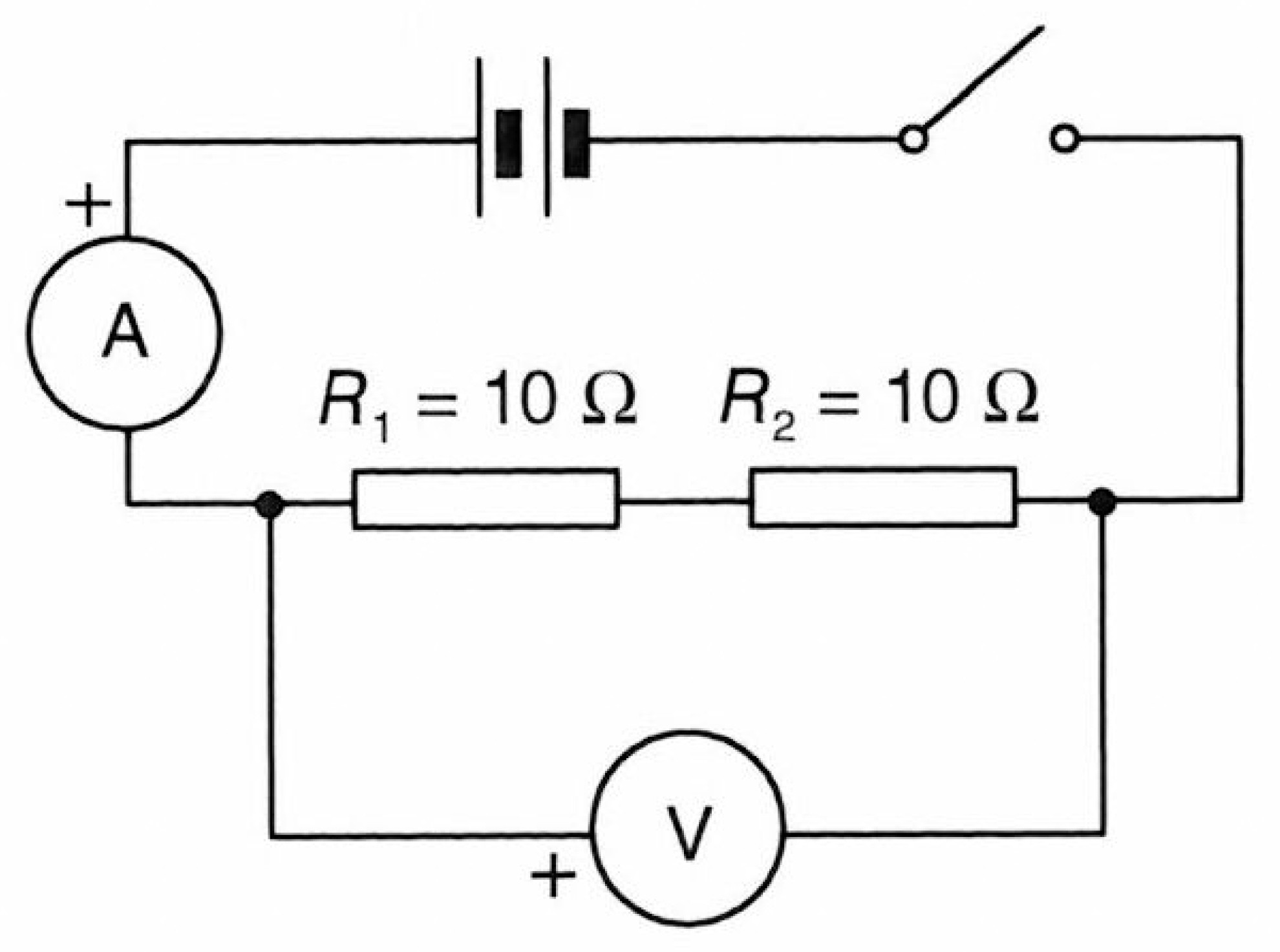
Select the correct action verb for each step in order:
-
1.two resistors (R1 and R2), 3 V battery, ammeter, and switch in series to form a closed circuit loop.
-
2.the voltmeter in parallel across the combination of two resistors to measure the total voltage V across them.
-
3.the switch to allow current to flow through the circuit.
-
4.the total circuit current I from the ammeter and the total voltage V from the voltmeter, then record them in the table.
-
5.the measurements using different resistance value pairs for R1 and R2.
Note: Ensure all connections are secure before closing the switch. Always turn off the switch when changing component settings.
4 Simulation

0.00 A

0.00 V
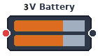

5 Ω
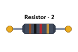
5 Ω

5 Result and Analysis
1. Tabulate the data in the table below.
| Trial Number | 1 | 2 | 3 | 4 | 5 |
|---|---|---|---|---|---|
| Resistance of resistor 1 (Ω) | - | - | - | - | - |
| Resistance of resistor 2 (Ω) | - | - | - | - | - |
| Voltage across two resistors V (V) | - | - | - | - | - |
| Current of circuit I (A) | - | - | - | - | - |
| Equivalent resistance (Req = V/I) (Ω) | - | - | - | - | - |
6 Discussion & Conclusion
1. How is the equivalent resistance Req of two resistors connected in series related to their individual resistances R1 and R2?
2. When an additional resistor is added in series to the circuit, what happens to the total equivalent resistance Req of the circuit?
3. How does the equivalent resistance Req of a series combination compare to the resistance of the largest individual resistor in the circuit?
4. If resistor R2 is removed or disconnected from the series loop, what will happen to the current in the circuit?